


An Indispensable Component in BTMS:
The Electric Compressor
1. The Role of the Electric Compressor in a BTMS
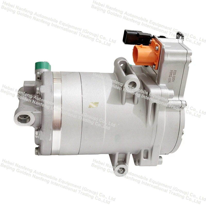
The electric compressor serves as the core power component of a vapor-compression refrigeration circuit. It draws in low-temperature, low-pressure gaseous refrigerant from the evaporator, compresses it into a high-temperature, high-pressure gas, and delivers it to the condenser, thereby driving the entire refrigeration cycle. In a Battery Thermal Management System (BTMS), it provides a cooling source for the chiller (a plate heat exchanger), which in turn cools the battery coolant. In heat pump-equipped systems, it can also facilitate heating through the use of a four-way reversing valve.
Key differences from traditional mechanical compressors: Powered by high-voltage DC electricity, it does not rely on an engine or a drive belt. It features an integrated inverter that drives a permanent-magnet synchronous motor (PMSM). Its rotational speed can be adjusted independently, and it can be started or stopped on demand-allowing for greater flexibility in vehicle integration and precise matching to thermal loads.
2. Operating Principle (Using a Scroll-Type Compressor as an Example)
Suction: Low-pressure gas from the evaporator outlet passes through a gas-liquid separator and enters a crescent-shaped suction chamber.
Compression: Driven by an eccentric shaft, the orbiting scroll moves in an orbital path (without rotating on its own axis). As it meshes with the fixed scroll, the enclosed crescent-shaped chambers move from the outer edge toward the center, with their volume gradually decreasing. This results in continuous gas compression, characterized by the absence of clearance volume and minimal airflow pulsation.
Discharge: Once compressed, the high-temperature, high-pressure gas is expelled through a discharge port at the center of the fixed scroll and enters the condenser to release heat.
Regulation: Cooling capacity (Q) is approximately equal to displacement × rotational speed × volumetric efficiency × cooling capacity per unit mass. Since rotational speed is the only continuously adjustable variable, variable-frequency speed control enables stepless capacity regulation from 10% to 100%.
Safety Limits: The maximum rotational speed is constrained by factors including discharge temperature, discharge pressure, and superheat; the controller uses these parameters to establish an upper limit for the compressor speed.

3. Application and Maintenance Essentials
System Selection: Allow a 20–30% margin based on the battery's peak heat generation, and verify cooling capacity derating at the maximum ambient temperature (55°C). For 800V architectures, prioritize systems using SiC (silicon carbide) inverters to reduce switching losses.
Component Matching: The electronic expansion valve (EXV) orifice size, chiller heat-exchange surface area, and compressor displacement must be selected in coordination; otherwise, a mismatch-such as an undersized valve paired with an oversized compressor-can lead to excessively high discharge temperatures.
Common Failures: Refrigerant leakage (low charge) causing high suction superheat and subsequent burnout; liquid slugging damaging the scroll set; DC-bus voltage drops triggering undervoltage protection; A2L refrigerant leaks exceeding safety concentration limits; and inadequate lubrication during prolonged low-speed operation.
Maintenance: Regularly inspect insulation resistance and housing seals, refrigerant charge levels and superheat, the condition of anti-vibration mounts (checking for aging), and the torque of electrical connectors.


