
What is the working principle of a plate heat exchanger?
An enhanced vapor injection (EVI) plate-type economizer is a core component in low-temperature heat pump and refrigeration units. Utilizing a plate heat exchanger as its foundation, it facilitates counter-flow heat exchange between two refrigerant streams. This process simultaneously achieves deep subcooling of the main liquid refrigerant and provides vapor injection into the compressor's intermediate pressure chamber-thereby enhancing low-temperature performance, lowering discharge temperatures, and improving overall energy efficiency.
I. Key Components and Structure
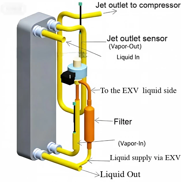
1. Gray rectangular unit (left): Plate heat exchanger (the economizer itself)
This serves as the primary medium for counter-flow heat exchange between the two refrigerant streams. It contains two sets of independent, sealed flow channels: one for the high-flow, high-pressure main liquid refrigerant, and another for the low-flow, low-temperature injection refrigerant. Heat is transferred between the two streams through metal plates, with no direct contact between the fluids.
2. Main liquid circuit ports (large-diameter yellow piping)
Liquid inlet: High-pressure liquid refrigerant at ambient temperature, arriving from the system's condenser, enters here.
Liquid outlet: The exit point for the subcooled, high-pressure liquid refrigerant. After being cooled via heat exchange, the liquid flows out toward the system's main electronic expansion valve (EXV) and evaporator.
3. Vapor injection branch components (small-diameter circuit)
EXV supply inlet: The entry point for the branch refrigerant; a small portion of the high-pressure liquid is diverted from the main circuit into this branch.
Filter (orange cylinder): Removes impurities and metallic debris from the branch refrigerant, preventing the downstream electronic expansion valve from becoming clogged.
Electronic Expansion Valve (EXV; blue and black component): The throttling device for the branch circuit. It reduces the pressure of the high-pressure liquid refrigerant, while its opening degree allows for precise control over the flow rate of the branch refrigerant.
Vapor injection outlet (to compressor): The exit point for the vaporized refrigerant. After absorbing heat and evaporating, the medium-pressure gaseous refrigerant flows out from here and is directed into the compressor's intermediate injection chamber.
4. Sensors
Injection Inlet Sensor: Measures the temperature of the refrigerant after it has passed through the branch-line expansion device but before it enters the plate heat exchanger.
Injection Outlet Sensor: Measures the temperature of the refrigerant at the outlet of the plate heat exchanger as it flows toward the compressor.
These two sensors, in conjunction with system pressure data, are used to calculate the superheat of the injection flow path, enabling closed-loop control of the electronic expansion valve.
II. Detailed Operating Principle
The unit consists of two circuits: the main liquid circuit and the auxiliary injection circuit. These circuits exchange heat via a counter-flow process within a plate heat exchanger, with electronic control logic ensuring stable operation.
1. Main Liquid Circuit (High-flow, primary circulation): High-pressure, ambient-temperature liquid refrigerant from the system condenser enters the main channel of the plate heat exchanger through the "Liquid Inlet" and flows from top to bottom. On the opposite side of the plates, the cooler refrigerant in the auxiliary circuit continuously absorbs heat, further cooling the main-line liquid and increasing its degree of subcooling (lowering its temperature below the saturation temperature corresponding to the condensation pressure). The subcooled, high-pressure liquid then exits through the "Liquid Outlet" and travels to the system's main electronic expansion valve, where it undergoes expansion before entering the evaporator to facilitate the heat-absorption process required for cooling or heating.
2. Auxiliary Injection Circuit (Low-flow, enthalpy-enhancing injection): A small portion of the high-pressure liquid refrigerant is diverted from the main high-pressure liquid line into the auxiliary circuit. It first passes through a filter to remove impurities and protect the expansion components. It then enters the auxiliary electronic expansion valve, where it undergoes expansion and a pressure drop-reducing from the high condensation pressure to an intermediate pressure-resulting in a significant drop in temperature and a transition into a low-temperature, two-phase (gas-liquid) state.
3. The low-temperature, two-phase refrigerant enters the auxiliary channel of the plate heat exchanger, flowing from bottom to top.
This creates a counter-flow heat exchange with the warmer liquid in the main circuit (counter-flow offers the highest heat-exchange efficiency and makes the most effective use of the temperature differential). As the refrigerant in the auxiliary circuit absorbs heat from the main-line liquid, it evaporates completely into a gaseous state. Ultimately, the superheated gaseous refrigerant at intermediate pressure exits through the "vapor injection port" and flows directly into the compressor's intermediate-pressure chamber. Here, it mixes with the suction refrigerant-which has already been compressed to an intermediate pressure-and the combined flow undergoes the remainder of the compression process.
4. Control Logic: The unit controller calculates the superheat of the vapor injection circuit based on temperature data from two sensors and the saturation temperature corresponding to the intermediate pressure. This value is used for closed-loop regulation of the electronic expansion valve (EEV) in the injection branch:
If the outlet superheat is too high, it indicates insufficient flow through the branch and underutilized heat-exchange potential; the controller opens the EEV further to increase the injected vapor volume, thereby enhancing the subcooling effect in the main circuit.
If the outlet superheat approaches zero, it indicates excessive flow through the branch, meaning the refrigerant has not fully evaporated. This poses a risk of liquid refrigerant entering the compressor; the controller closes the EEV to prevent liquid slugging, which could damage the compressor.
Functions of the plate-type economizer for vapor-injected cycles:
Increases the refrigerant circulation rate under low-temperature operating conditions, significantly boosting the unit's heating/cooling capacity in such environments.
Introduces low-temperature gaseous refrigerant, which helps lower the compressor discharge temperature.
Increases the degree of subcooling in the main refrigerant circuit, raising the heat-exchange capacity per unit mass and significantly improving the system's Coefficient of Performance (COP).
Facilitates real-time adjustment of the injected vapor volume through closed-loop control, ensuring efficient and stable operation of the unit across its entire operating range.


