Working Principle of Electronic Water Pumps
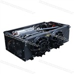
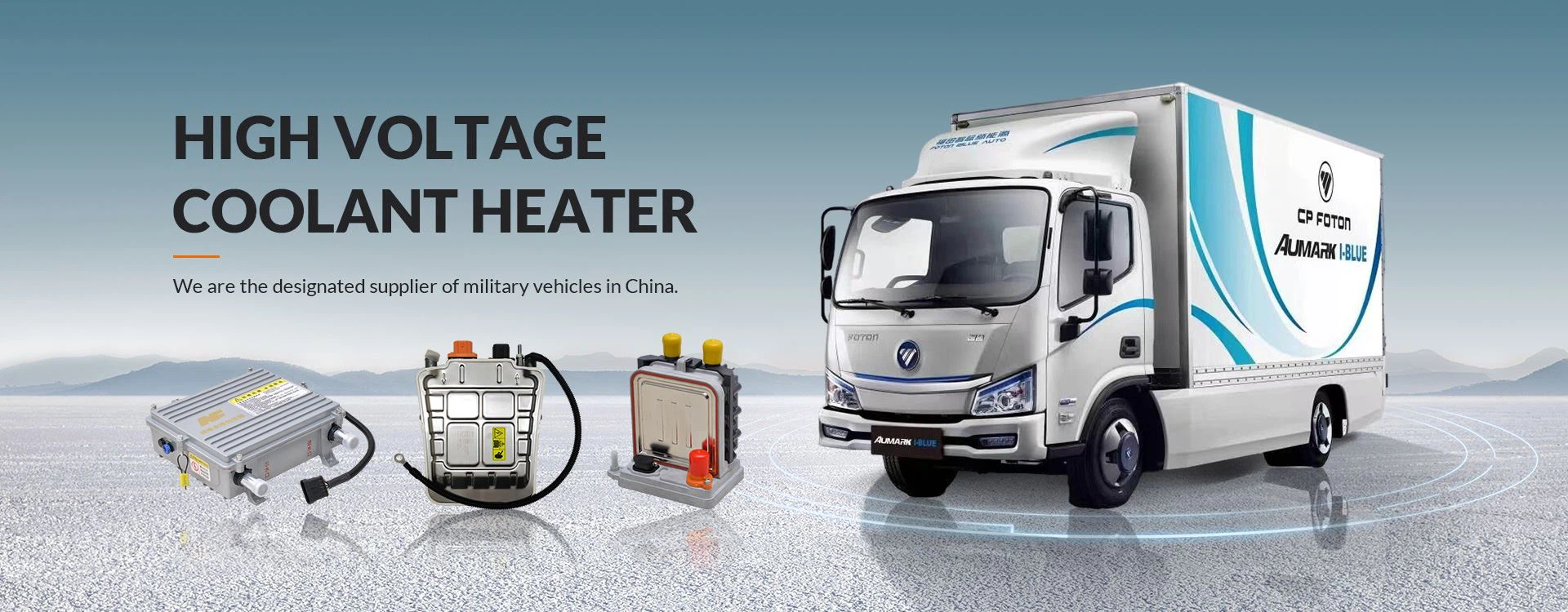
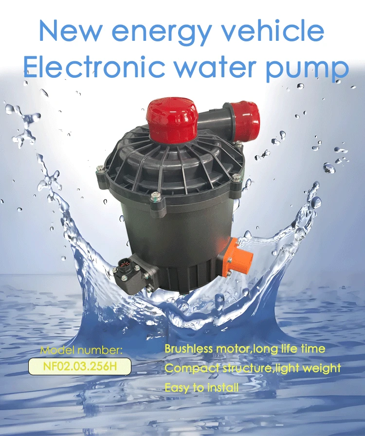
Electronic water pumps differ from traditional mechanical belt-driven water pumps in gasoline vehicle engines. They rely on an onboard high-voltage/low-voltage DC motor to independently circulate and transport coolant. They are a core component of the fluid transport system in the water-cooled thermal management system of new energy vehicles, often used in conjunction with the electric compressor, water-cooling plate, radiator, heat exchanger, and PTC heater mentioned earlier.

Basic Working Principle of Electronic Water Pumps
1. Mechanical Principle of Fluid Transport (Centrifugal Pumps are Mainstream)
Over 95% of automotive electronic water pumps adopt a centrifugal structure, with the impeller as the core working component:
The motor drives the impeller to rotate at high speed, drawing coolant into the center of the impeller;
The impeller blades apply centrifugal force to the liquid, causing the coolant to be thrown out at high speed from the center towards the outer edge of the pump body, simultaneously increasing pressure and flow rate;
The high-pressure coolant is collected by the pump casing and transported from the outlet to various heat dissipation/heat exchange components;
The cooled coolant, after being cooled by the pipeline, flows back to the water pump inlet, forming a closed-loop water circulation.
Precise Control of Coolant Flow and Water Pressure: By adjusting the motor speed, coolant flow and water pressure can be precisely controlled, achieving stepless flow regulation.
2. Electrical Drive Working Principle
The entire system is an integrated structure consisting of a hydraulic unit, a drive motor, and a built-in drive controller (drive board).
Power supply options include: low-voltage 12V/24V and high-voltage DC (300~900V, compatible with vehicle 400V/800V platforms).
The drive board receives LIN/CAN bus signals from the vehicle's VCU, BMS, and MCU, adjusting the motor speed in real-time based on battery temperature, motor temperature, and cabin coolant temperature.
The mainstream motor type is a brushless DC motor (BLDC), eliminating the carbon brush wear structure compared to brushed motors. The drive board drives the three-phase stator through an inverter circuit, using Hall effect sensors for closed-loop speed control.
It features built-in overcurrent, overheat, stall, dry-run, and insulation fault protection. Abnormal conditions are reported to the vehicle controller, and the system shuts down for self-protection.
Embedded Protection
Protection against overcurrent, overheat, stall, dry-run, and insulation faults is provided. Abnormal conditions are reported to the vehicle controller, and the system shuts down for self-protection. Synergistic Relationship between Electric Water Pump and Electric Compressor: The electric compressor is responsible for heat transfer (cooling/heating), while the electric water pump is responsible for the distribution of cold/heat in the water circuit. Together with the heat exchanger, water-cooled plate, and valves, they form a complete integrated thermal management system for the vehicle, jointly controlling the temperature of the battery, motor, and cabin systems.